LEO / GEO SATCOM Interference
- Mar 4, 2017
- Article
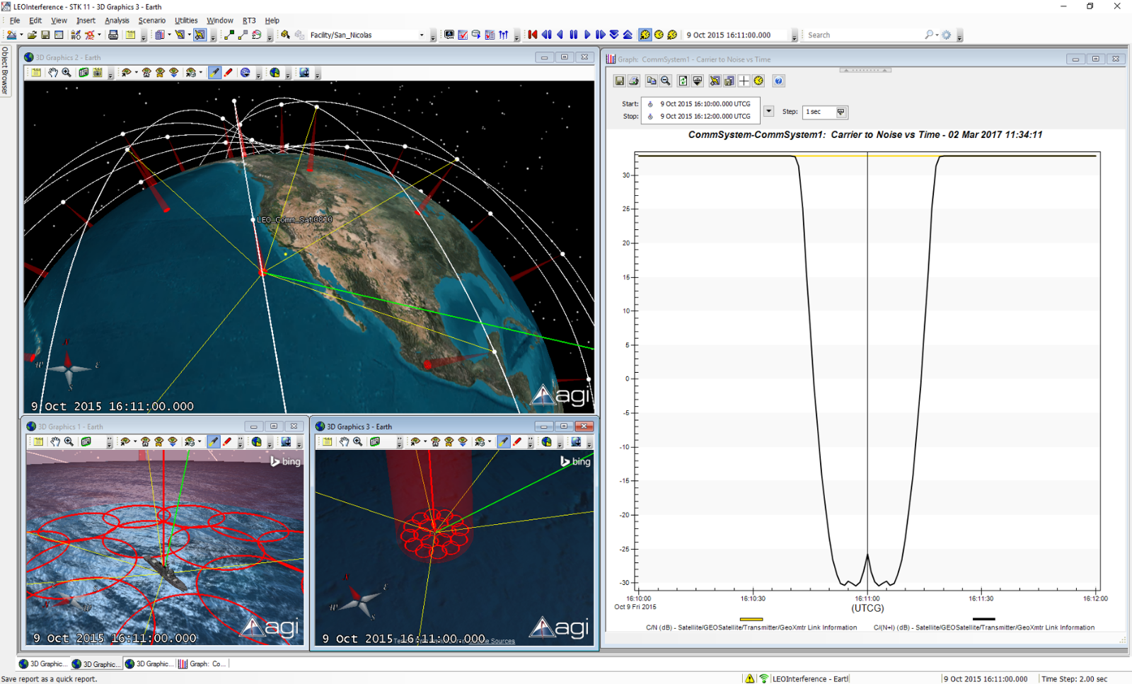
STK can be used to model and analyze the interference from a constellation of Low Earth Orbiting (LEO) satellites on the communications link between a Geostationary satellite to a ground link. In this example, a Geostationary satellite was configured with a transmitter with access to a receiver on a ground platform. A LEO satellite constellation was built by using the Walker Tool, available through the STK SatPro module, and each bird was configured with a transmitter. In this example, a multibeam transmitter was included on each LEO spacecraft as interferers. The image below shows the 3 dB contours of the multibeam transmitter surrounding a ship receiver. A CommSystem object was used to process the interference of these LEO transmitters on the desired space-to-ground link represented by a green line in the figure below. A red line represents the interference link. The graph shows the C/(N+I) or Carrier to Noise Plus Interference Ratio when the ship-based receiver is in the center of the satellite footprint (about 60 dB compared to the static C/N).
This example was created based on the New Features in STK 11 Tutorial. The objects that were added are as follows:
This example was created based on the New Features in STK 11 Tutorial. The objects that were added are as follows:
- Default Geostationary satellite and default Complex Transmitter with Antenna pointed at the DDG ship.
- Default Medium Receiver with 40 dB Gain on the DDG ship.
- Multibeam Transmitters on each of the LEO_Comm satellites.
- Constellation to contain all of the multibeam transmitters.

