Radar signal polarization and complex scattering Radar cross section
- Jul 28, 2014
- Article
-
 Radar
Radar
Polarized signals in Radar applications help obtain better information about the radar target. Different target geometries and material characteristics respond differently to polarized signals. Questions have been raised about how STK handles polarized signals and complex scattering RCS for targets. STK/Radar offer high fidelity polarization modeling in radar signals as well as the complex scattering properties of the targets. The target’s Radar Cross Section (RCS) can be constant, symmetric, completely aspect dependent or dynamic. The position and attitude of the target determine the RCS as illuminated by a transmitter and as seen by the radar receiver. STK/Radar scenario can model dual channel transmitters and/or dual channel receivers. Two channels represent the signals with a polarization from an orthogonal set (e.g. RHC/LHC or vertical/horizontal). The primary transmit channel polarization is selected by the user, and the secondary channel polarization is set by STK to be orthogonal to the primary channel. The radar transmit side and receive side polarizations can be set independently. Orthogonal polarization channel feature allows the user to model a second transmitted signal with similar characteristics but different polarization. On the receive side, the receiver can be single or dual channel. In the case of dual channel system, the first channel is the primary channel, and the user selects its polarization. The secondary channel polarization is set by STK to be orthogonal to the primary channel.
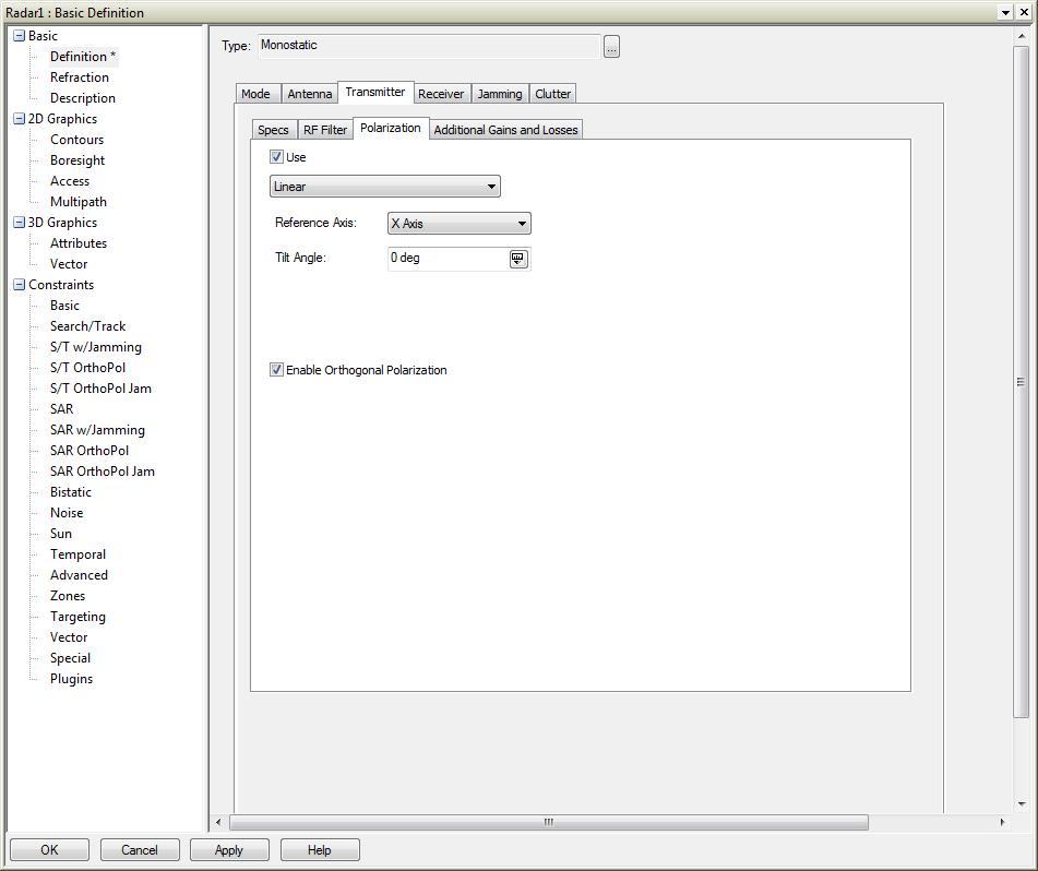
 Figure 1 Radar transmit side polarization settings

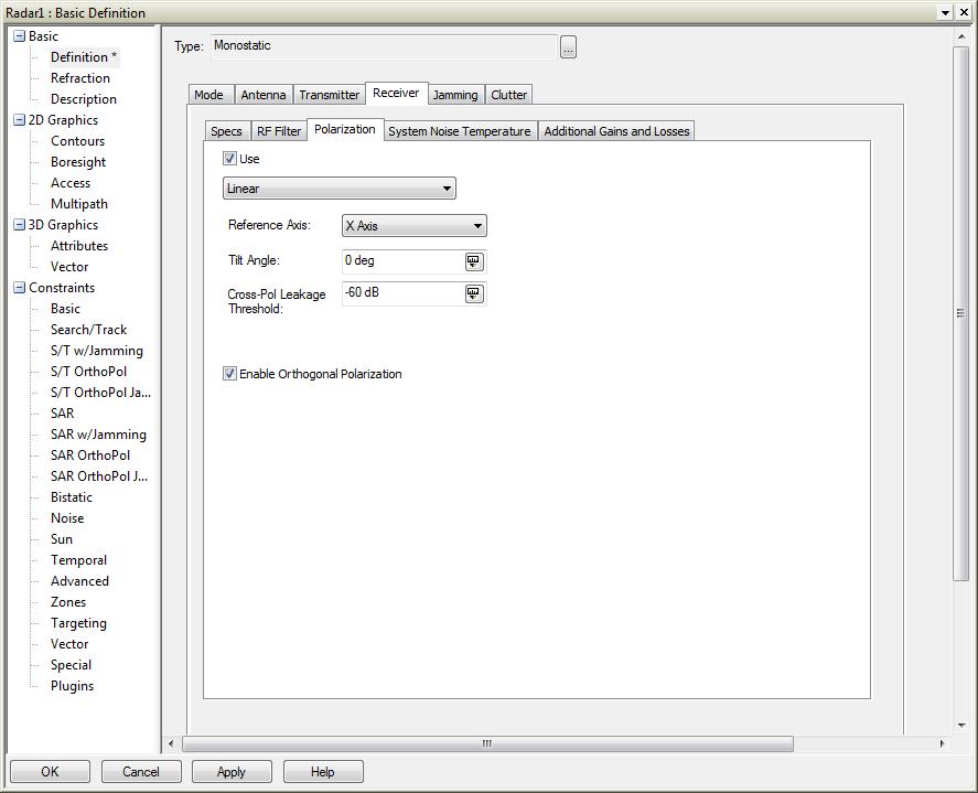
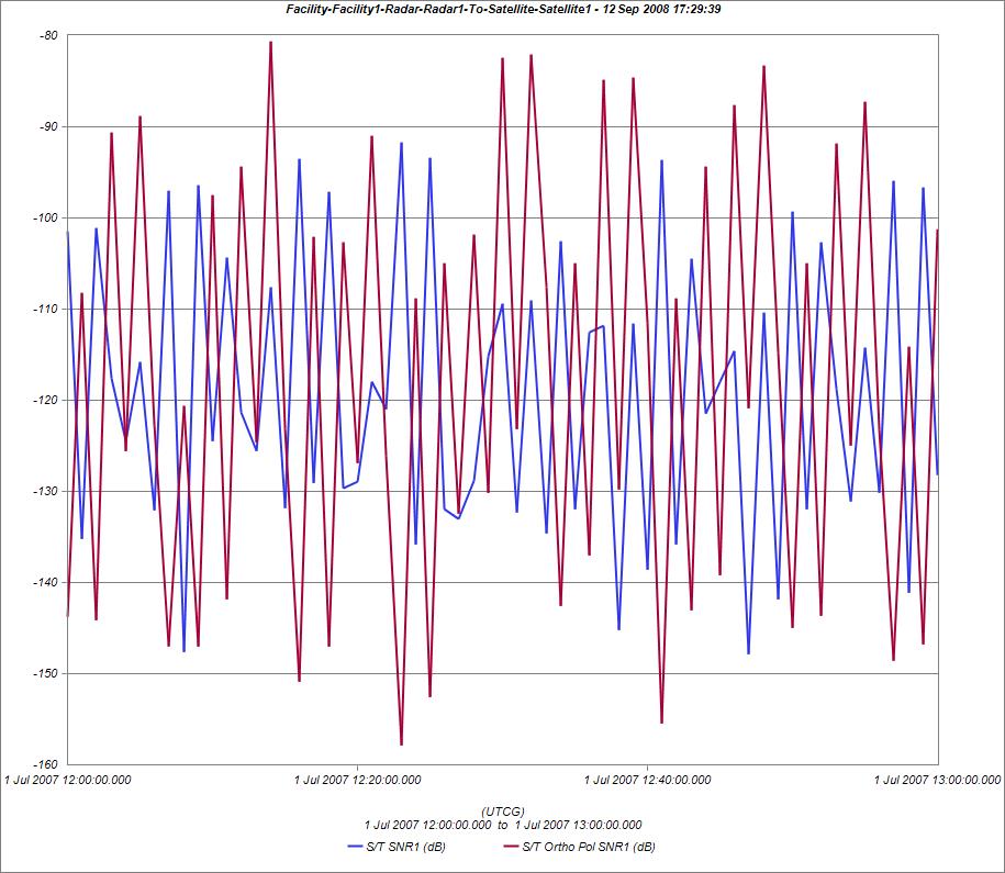
Figure 2, shows the radar receive side polarization settings. Receiver polarization setting allows for cross pol leakage from one channel into another channel. Both transmit and receive sides show the option for an orthogonal channel. This helps model systems with different configurations. Possible combinations are below: The above chart shows the primary channel S/N and the orthogonal channel S/N changing over time for a spinning satellite used as a target.
 Figure 1 Radar transmit side polarization settings
Figure 2, shows the radar receive side polarization settings. Receiver polarization setting allows for cross pol leakage from one channel into another channel. Both transmit and receive sides show the option for an orthogonal channel. This helps model systems with different configurations. Possible combinations are below:
- A radar system can be single channel with one transmitter and on the receiver.
- A radar system may have one transmit channel and dual channel receiver. This will determine cross pol leakage into orthogonal channel.
- A Radar system with dual channel transmitter and a single channel receiver will receive the primary channel signal as well as the cross pol leakage from the orthogonal signal into the primary channel.
- A system with dual channel transmitter and dual channel receiver will model two transmitted signals. The dual channel receiver will receive the respective primary and orthogonal channel signals as well as the cross pol signals.
- Constant target RCS. This can help determine radar sensitivity threshold and usable range, etc.
- Symmetric RCS. The RCS is symmetric around an axis. For example, target is a cylinder.
- Aspect dependent Real valued. RCS matrix defies the complete aspect dependent variation of the RCS.
- Aspect dependent Complex valued. RCS matrix has complex-valued elements.
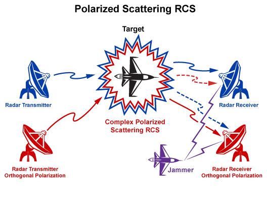
- Complex scattering RCS. Each element of the aspect dependent RCS matrix is a 2x2 complex scattering matrix. Scattering matrix defines the energy reflected by each polarized signal (primary & orthogonal) channel as well as the conversion of signal polarization from primary pol into orthogonal pol and vice versa due to the geometry and material characteristics.
 The above chart shows the primary channel S/N and the orthogonal channel S/N changing over time for a spinning satellite used as a target.

